HomeHub, 3 – ESP8266 and Sonoff Basic
I’ve built a home automation system from scratch.
This is the 3rd part of a series of posts
I’m writing these lines as a complete beginner in the Arduino and electronics world so take this more as a journal of my findings than a guide.
Now that we have a working, configured Raspberry Pi running we’d like to set up and get the wifi controllers in order and connect a sensor and read the data from it.
In this part we’ll see how to:
- Setting up the D1 mini
- Get the Arduino IDE ready
- Create a Hello World sketch
- Connect the D1 mini to the wifi
- Get Up and Running with the Sonoff Basic R2
Wemos D1 mini or similar #
Do it over the air, get something small. These were the guides when I was on the lookout for some parts.
There is a lot of love about the Wemos D1 mini out there, so I’ve found something similar but a bit cheaper, as breaking the bank for this is/was not an option, so ordered something from China that really looks like the original Wemos.
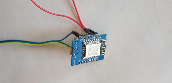
This dev board can be powered from a 3.3V source and also from a 5V USB connection, making the development part very convenient as the USB is suitable for code uploading as well.
The board can produce either 3.3V or 5V on its output pins ready for consumption, so keep this in mind when looking for sensors or other stuff that should be driven by boards circuit.
My first sensor of choice was the DHT-22 which is a temperature and humidity sensor.
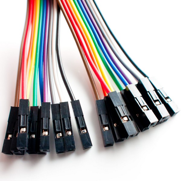
To connect the whole bunch together it’s useful to have some Dupont wires with female to female ends at hand.
So where to start:
First, solder the header connectors to the board.
Use a pin layout as a reference to see which pin is used for what.

The pins denoted with Dx are digital pins as opposed to the ones denoted with Ax, they are analogue pins.
There are some special pins like the RST which is used to send a reset signal to the board.
In my case I’m interested in a digital pin as my sensor has a digital output.
When connecting the sensor to the board keep in mind that this is a DC circuit, so – unless you want to see some smoke – + goes to + and - to -. In this case 3.3V or VCC to + and the GND (ground) to -. Connecting with the incorrect parity will damage the board and the sensor.
Arduino IDE #

So far we have a board ready to be powered up and a sensor that is ready to be connected.
To upload some code and make your hardware do something download the brilliant IDE for Arduino.
This requires a bit of a setup before first use.
To bring support for ESP8266 chip to the Arduino environment use the boards manager to install additional 3rd party platforms.
Enter the following to the “Additional Boards Manager URLs” field under preferences/settings menu.
https://arduino.esp8266.com/stable/package_esp8266com_index.json
And then don’t forget to select your board under “Tools/Board”. For me the Generic ESP8266 Module worked perfectly.
Select 9600 for Baud rate for now.
Hello world of Arduino land #
Each tech faction has its own hello world type of dummy application to see that everything is good to go, in this case Blinking the LED is the one to go for.
We’ll write all our code in one single file called a sketch.
The code for blinking the led looks like this:
// the setup function runs once when you press
// reset or power the board
void setup() {
  // initialize digital pin LED_BUILTIN as an output.
  pinMode(LED_BUILTIN, OUTPUT);
}
// the loop function runs over and over again forever
void loop() {
  // turn the LED on (HIGH is the voltage level)
  digitalWrite(LED_BUILTIN, HIGH);
  // wait for a second
  delay(1000);
  // turn the LED off by making the voltage LOW
  digitalWrite(LED_BUILTIN, LOW);
  // wait for a second
  delay(1000);
}
The concept is to turn the LED on for one second and then turn it off for another second creating the blinking effect. The LED_BUILTIN maps to the local pin of the board which is connected to the LED.
To print something to the “console”, for debugging purposes place these lines to the code and you’ll see the output in the Serial Monitor.
void setup() {
  ...
  Serial.begin(9600);
  ...
}
void loop() {
  ...
  Serial.println("Hello world");
}
Notice the 9600 is the same baud rate as in the connection setup.
Once the code looks ok, verify and upload.
When the upload completes the LED should start blinking immediately.
Connect to WIFI #
To set up the wifi connection use a 3rd party library that takes care of the connection and handles the retries and errors properly.
Never store your Wifi credentials in the sketch, use a header file instead and include it. This way when the code gets checked in to version control like git and uploaded to a remote repo the passwords won’t be made public.
As later I’ll be using MQTT as well, I use a library that handles both the wifi connection and the MQTT broker by Patric Lapointe.
Libraries can be installed through the Library Manager.
To setup the connection, create a connection object, include the credentials, and call the client loop in the loop method.
#include "secrets.h"
#include "EspMQTTClient.h"
EspMQTTClient client(WIFI_SSID, WIFI_PASSWORD, MQTT_BROKER_IP, MQTT_USERNAME, MQTT_PASSWORD, "Sonoff_5");
void loop() {
  client.loop();
}
the secrets.h is the header file where I keep the wifi and messaging broker credentials. To allow the compiler to find it create a directory in the following location:
/Users/<yourusername>/Documents/Arduino/libraries/
and define your secrets like this:
// /Users/<yourusername>/Documents/Arduino/libraries/MyFolder/secrets.h
#define WIFI_PASSWORD "secretPassword"
Connect a sensor to the D1 mini #
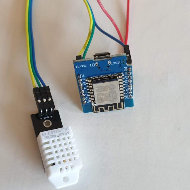
Driving the sensor from the wifi micro-controller, connect the power and pick a digital pin for the “out” leg of the sensor.
#include "DHTesp.h"
DHTesp dht;
void setup() {
  ...
  // Start sensor
  // Connect DHT sensor to GPIO 4 (D2)
  dht.setup(4, DHTesp::DHT22);
}
void loop() {
  ...
  float newTemp = dht.getTemperature();
  float newHum = dht.getHumidity();
  String status = dht.getStatusString();
  delay(2000); // min sampling rate
}
Let’s see what is happening in the code. First, import the DHTesp library, I’m using the one by beegee_tokyo.
While setting up the sensor, there is this weirdness about referring to the GPIO pins. On the board it’s usually the Dx kind of notation, which you’ll need to map to the corresponding GPIO number using the pinout diagrams, in my case I choose the D2 pin that maps to GPIO 4 in: dht.setup(4, DHTesp::DHT22).
Always read the specs as this sensor has some limitations around how frequently it yields new data, with the DHT22 the sampling rate is 0.5 Hz or once every 2 seconds.
This particular unit can measure temperature and humidity and provides a sensor status which is like a health check.
This library returns the temperature value in Celsius.
Sonoff Basic R2 #
To get started with the Sonoff we’ll take similar steps to the D1 mini. Take it apart and locate the four pin holes, marked with VCC, GND, RX, TX, solder the header connectors.
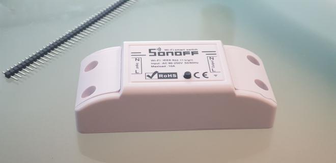
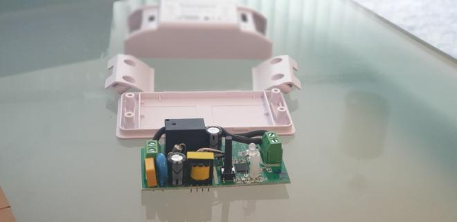
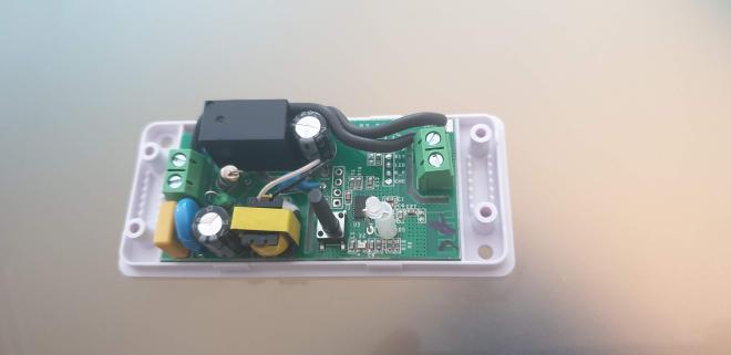
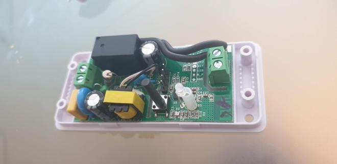
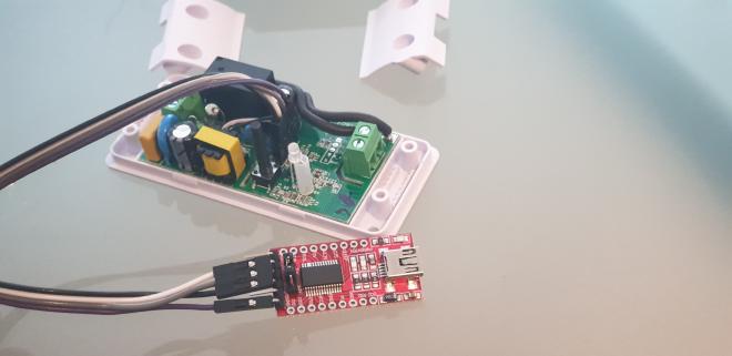
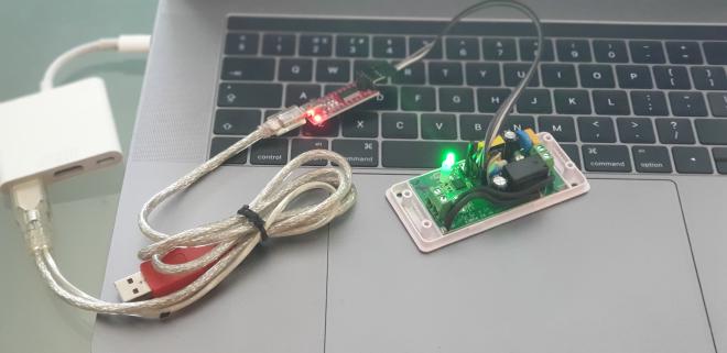
To communicate with your Sonoff you’ll need an FTDI USB to Serial converter.
Connect it like this:
VCC – VCC ( + )
GND – GND ( – )
RX – TX (Receive to Transmit)
TX – RX (Transmit to Receive)
To get the Sonoff connected to your wifi follow the steps described in the D1 mini section, it’s the same.
Please note that by flashing your own lines of code on the Sonoff you’ll lose the original software that the unit was shipped with.
Why Sonoff? #
Why not a 5V relay module like this one?
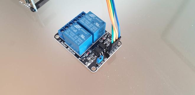
Well I can’t say I haven’t tried. And I’ve learned one of if not the biggest problems with this smart home hype. It may be obvious to some, for me it was trial and error.
You need low-voltage DC, to power the controllers.
Sometimes it makes sense to get a cheap USB mobile charger and use that to power the wifi controller (5V) and use the wifi boards to drive the relay module. And the relays will switch the high voltage AC power, for example your lights, coffee machine, fish tank or what not. Most often than not, finding an extra socket for the USB charger is problematic or just doesn’t make any sense.
What makes more sense is to get the power needed for the controller from the mains. Which is what the Sonoff does. But can you do it safely? If not, then don’t do it.
To experiment with this a little and to see if I can get this to work I got a couple of 220V AC to 5V DC isolated step-down buck converters, some prototyping PCB boards, suitable wires for the high and low voltage parts and put together these with the relay module and one of the D1 minis. And finally closed everything in a project box, it’s live mains after all.
It was working fine, but the size of it.. ohh boy. and it’s not pretty and most importantly it’s not safe. Researching the matter more I should have used thermistors, voltage regulator and other part to make it more safe and less of a fire hazard.
And even though the one I made was working fine, I could see how making 10-15 of these could easily go wrong. I wouldn’t have slept very well.
So I decided to ditch these large ugly boxes of fire hazards and used something that’s nicely designed, small, and adequately tested.
Conclusion #
In this part of the series we saw how to wire up a D1 mini (or similar) wifi controller to a DHT22 sensor, connect it to your wifi and make it do something by first uploading a bit of code to blink the LED and later to use the code to read the sensor data.
We went through how to upload your custom code to the great Sonoff Basic R2, the software steps were similar to the D1 mini, the main difference was in the way of connecting to the board, where we needed an FTDI USB to Serial converter.